The on-board electrical system in private or commercial motor vehicles is usually laid out in a 12V or 24V voltage range. Individual high powered systems (e.g. motors or starters) may require currents of several 100A. These high currents are switched indirectly via relays placed close to the appliance. This offers the advantage of lower line losses and that switches do not have to be designed for high loads. Additionally, the relay can also be addressed via a control unit or carry out small control functions by itself.
Depending on the installation location in the vehicle, not only is the space available limited, but the environ- mental conditions also pose a major challenge when selecting the right relay. In the engine compartment these are mainly the high temperatures and vibrations; in other places the relay can be exposed to dust or moisture. A corresponding degree of protection (e.g. IP64 for encapsulated or sealed housings) may be required.
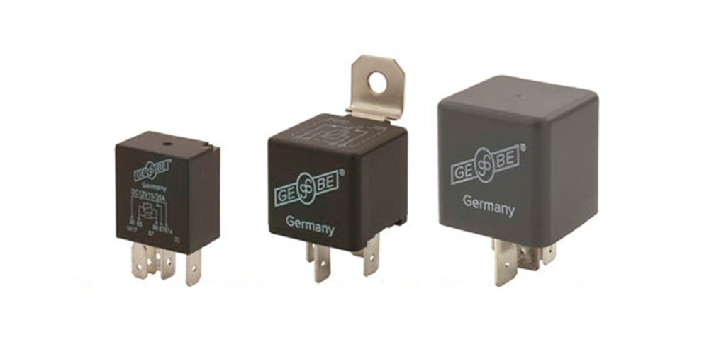
Today, standardized designs have been largely established for the respective purposes:
- Micro Relays: are particularly com- pact and designed for nominal switch- ing currents of up to around 25A
- Mini Relays: offer a higher load capacity of up to around 75A in a compact size
- Power Relays: for high currents up to several 100A
Even though relays are mechanically robust and designed for a service life of several 100,000 switching cycles, they are subject to wear. This comes from microscopically small arcs that are formed with every switching process. In the worst case, this can lead to the formation of massive layers of corrosion products over time, which continually increases the contact resistance and can ultimately destroy the relay due to overheating.
Thanks to the design with standardized plug contacts, quick replacement is possible in the event of service. It should be noted that the assignment of the contacts is not uniform across manu- facturers and must be precisely aligned. In addition, the coils of some relays are equipped with attenuators (resistors or diodes), which affect, among other things, the timing of the switching process slightly. Here too, care must be taken to ensure an exact replacement.
In addition to their pure function as switches, relays can also take on certain control functions independently. In the simplest case this is e.g. B. used for flasher relays in which a regularly timed switching process takes place. With wipe-wash interval relays, the wiper motor is activated at variable intervals depending on the switch position. There are also time relays (timers) that carry out a specific switching function with a set time delay or advance delay (e.g. fan delay).
The voltage-dependent relay (BSR relay) allows two batteries to be charged at the same time. If a voltage of over 13.3V is reached while the engine is running, the relay is activated and the second battery is charged in addition to the primary battery. If you switch off the engine, the on-board voltage falls below 12.8V and the relay separates the starter battery from the second battery. This system not only prevents unwanted discharge of the starter battery, it also protects the sensitive electronics connected to the secondary battery from voltage peaks that can occur when starting the engine.
