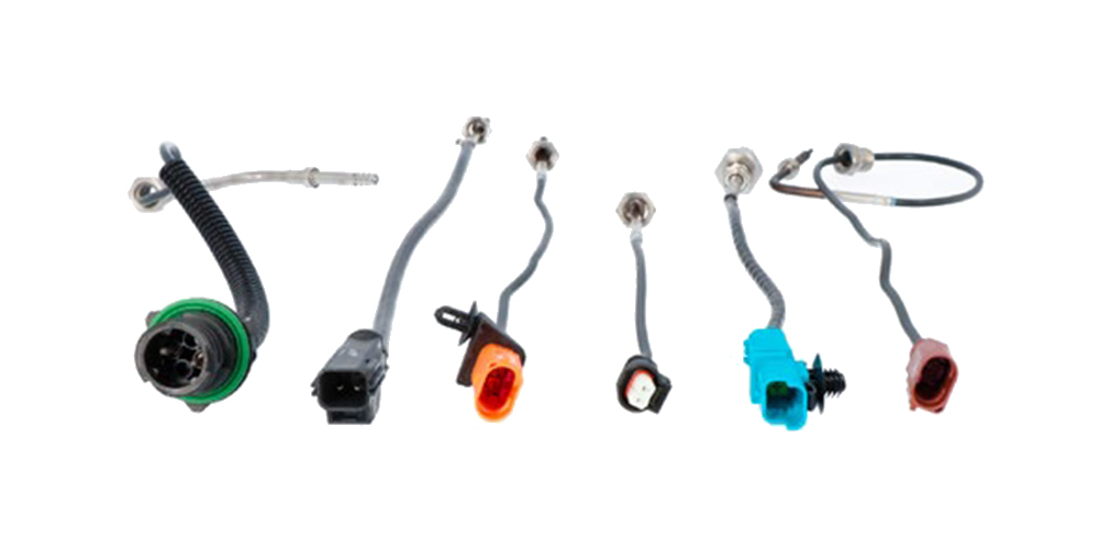
An exhaust gas temperature sensor records the temperature
- at the turbocharger,
- at the EGR module,
- before and after the 3-way-catalytic
converter, NOx adsorber, SCR converter, - before and after the particle filter.
However, the defective exhaust gas temperature sensor is not always immediately recognized as a fault in the vehicle.
As an example, since 2003 diesel engines need to have an OBD monitoring function: Many vehicle manufacturers use two exhaust gas temperature sensors to monitor the oxidation catalytic converter, which are installed before and after the converter.
In order to start the chemical process of combining carbon monoxide (CO) and unburned hydrocarbons (HC) with the oxygen (O2) in the oxidation catalytic converter, some manufacturers subsequently inject additional fuel into the warm engine at a constant load using the signal from the engine control unit.
When HC and CO oxidize, heat is generated. As a result, the exhaust gas temperature increases significantly after the catalytic converter. If a temperature is detected that is too low due to a defect in the rear sensor, there will be a deviation from the specified reference values. As a result, the engine control unit interprets a decreasing effectiveness of the catalytic converter and switches on the OBD light. If the oxidation catalytic converter is then replaced, the OBD lamp comes on again after a short time and the customer legitimately comes back to the workshop. Simply checking the measured values and replacing the sensors would have avoided the complaint.
A distinction is currently made between NTC (negative temperature coefficient) and PTC (positive temperature coefficient) sensors. With NTC the resistance decreases as the temperature increases, with PTC the resistance increases.
It is possible to check the sensors thanks to the measured values stored in databases by the vehicle manufacturers and a simple resistance measurement on the two connecting cables with a multimeter. If the sensor is installed in an invisible area, it helps to compare the cable colours on the plug connections with the existing circuit diagrams, as the different sensors are usually connected with different coloured cables. If a fault is detected, the sensor must then be exposed and visually inspected.
